Laplace transform

The Laplace transform of a continuous time signal x(t)\text{x}(t) can be expressed as: X(s)=∫−∞∞x(t)e−stdt\text{X}(s) = \int_{-\infty}^{\infty} \text{x}(t) e^{-st} dt

Where s=σ+jωs = \sigma + j \omega represent a complex frequency on a complex number plane.

e−st=e−(σ+jω)t=e−σte−jωt e^{-st} = e^{-(\sigma+j\omega)t} = e^{-\sigma t} e^{-j\omega t}

We can clearly see that

Re{e−st}=e−σtcos⁡(ωt)Re\{e^{-s t}\} = e^{-\sigma t} \cos(\omega t)

Im{e−st}=−e−σtsin⁡(ωt)Im\{e^{-s t}\} = - e^{-\sigma t} \sin(\omega t)

Eigenfunctions of LTI systems

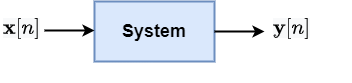
Let the system h(t)h(t) be a linear and time invariant (LTI) system and the input x(t)=est\text{x}(t) = e^{st}. The output y(t)\text{y}(t) of this system can be written as

drawing

Error in LaTeX ' \text{y}(t) = e^{st} \* h(t) ': KaTeX parse error: Undefined control sequence: \* at position 23: …y}(t) = e^{st} \̲*̲ h(t)

       =∫_−∞∞h(τ)es(t−τ)dτ~~~~~~~ = \int\_{-\infty}^{\infty} h(\tau) e^{s(t-\tau)} d\tau

       =∫_−∞∞ h(τ) est e−sτ dτ~~~~~~~ = \int\_{-\infty}^{\infty}~ h(\tau) ~e^{st}~ e^{-s\tau} ~d\tau

       =est∫_−∞∞ h(τ) e−sτdτ~~~~~~~= e^{st} \int\_{-\infty}^{\infty}~ h(\tau)~ e^{-s\tau} d\tau

       =H(s)est~~~~~~~ = H(s) e^{st}

este^{st} is known as eigen function for LTI system and it preserves the shape of the input signal.

Example - All RLC circuits are LTI systems. Recall that for any AC source, we always get sinusoidal voltage/current across any part of the circuit. The amplitude and phase might change but the shape remains the same

The Laplace transform has always two parts:

  1. Mathematical expression

  2. Region of convergence: the region in the complex s-plane, where the mathematical expression is valid.

Example

  1. x(t)=e−tu(t)\text{x}(t) = e^{-t} u(t)

    Solution: The Laplace transform is given as:

                      X(s)=∫_−∞∞x(t)e−stdt~~~~~~~~~~~~~~~~~~~~~~\text{X}(s) = \int\_{-\infty}^{\infty} \text{x}(t) e^{-st} dt

                               =∫_0∞e−te−stdt~~~~~~~~~~~~~~~~~~~~~~~~~~~~~~~ = \int\_{0}^{\infty} e^{-t} e^{-st} dt

                               =∫_0∞e−(s+1)tdt~~~~~~~~~~~~~~~~~~~~~~~~~~~~~~~ = \int\_{0}^{\infty} e^{-(s+1)t} dt

                               =1s+1~~~~~~~~~~~~~~~~~~~~~~~~~~~~~~~= \frac{1}{s+1}

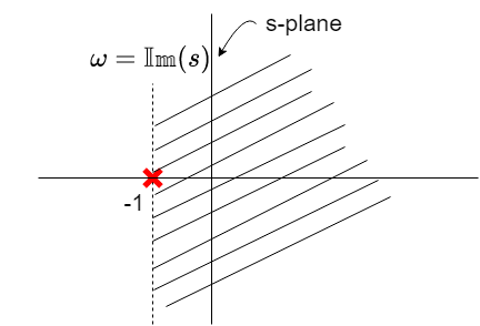
  • Region of convergence (ROC) is region in the s-plane where the above expression is valid.

  • The expression is valid if Re{s+1}>0Re{\{s+1\}} > 0 i.e. Re{s}>−1Re{\{s\}} > -1. s=−1 s = -1 is a point of singularity.

drawing

Let X(s)\text{X}(s) be the polynomials in ss variable as below:

X(s)=A(s)B(s)\text{X}(s) = \frac{\text{A}(s)}{\text{B}(s)}

Roots of A(s)\text{A}(s) i.e. A(s)=0→ \text{A}(s) = 0 \rightarrow zeros

Roots of B(s)\text{B}(s) i.e. A(s)=0→\text{A}(s) = 0 \rightarrow poles

Note: Poles play important role to decide ROC. ROC cannot have poles within them.

Exercise

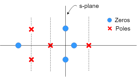
What is the ROC for the pole-zero plot shown below?

drawing

Linear constant coefficient differential equations (LCCDE)

Any linear constant coefficient differential equations (LCCDE) in Laplace domain can be expressed as ratio of polynomials.

Example: Let x(t)=dydt+a y(t)\text{x}(t) = \frac{d\text{y}}{dt} + a~\text{y}(t)

Taking Laplace transform of the above equation:

           X(s)=sY(s)+aY(s) ~~~~~~~~~~~\text{X}(s) = s\text{Y}(s) + a \text{Y}(s)

           X(s)=(s+a) Y(s)~~~~~~~~~~~ \text{X}(s) = (s + a)~ \text{Y}(s)

           Y(s)=X(s)s+a~~~~~~~~~~~\text{Y}(s) = \frac{\text{X}(s)}{s + a}

           H(s)=Y(s)X(s)=1s+a~~~~~~~~~~~ \text{H}(s) = \frac{\text{Y}(s)}{\text{X}(s)} = \frac{1}{s + a}

Here H(s)\text{H}(s) is known as transfer function or system function.

Application of Laplace transform for system analysis

drawing

Let h(t)h(t) be the system with input x(t)\text{x}(t) and output being y(t)\text{y}(t).

     y(t)=x(t)∗h(t)~~~~~\text{y}(t) = \text{x}(t) * h(t)

The system input-output relationship in Laplace transform can be expressed as:

   Y(s)=X(s)H(s)~~~\text{Y}(s) = \text{X}(s) \text{H}(s)

We are interested in additional system properties and their effect on impulse response and system function

Causality of LTI system

For LTI system to be causal, we should have

    h(t)=0,  ∀ t<0~~~~h(t) =0, ~~\forall~ t<0

    y(t)=x(t)∗h(t)=∫−∞∞x(τ)h(t−τ)dτ~~~~ \text{y}(t) = \text{x}(t)*h(t) = \int_{-\infty}^{\infty} \text{x}(\tau) h(t-\tau) d\tau

For Causality: we should only use x(τ)\text{x}(\tau) for τ≤t\tau \leq t

τ>t, h(t−τ)=0\tau > t,~ h(t-\tau) = 0

h(t)=0  ∀ t<0h(t) = 0~~ \forall~ t<0

  • For a causal system (i.e.,h(t)h(t) is a right-sided signal) , what is nature of H(s)\text{H}(s) ?

  • ROC of H(s)\text{H}(s) will be right-sided plane. (Converse is not true in general)

  • For a system with rational system function, causality is equivalent to the ROC being right-sided plane to the right of right most pole.

Example:

  1. H(s)=1s+1 and Re{s}>−1\text{H}(s) = \frac{1}{s+1}~\text{and}~ Re\{s\} > -1

          h(t)=e−tu(t)~~~~~~~~~~h(t) = e^{-t} u(t) (Causal)

  1. H(s)=ess+1\text{H}(s) = \frac{e^s}{s+1} and Re{s}>−1Re\{s\} > -1

          h(t)=e−(t+1)u(t+1)~~~~~~~~~~h(t) = e^{-(t+1)} u(t+1) (Non-causal)

Stability of LTI system (bounded input bounded output)

An LTI system is said to be stable if

∫∞∞∣h(t)∣dt<∞\int_{\infty}^{\infty} |h(t)| dt < \infty

i.e. h(t)h(t) is absolutely integrable

We know Laplace transform is given as:

    H(s)=∫∞∞h(t)e−stdt~~~~\text{H}(s) = \int_{\infty}^{\infty} h(t) e^{-st} dt

H(s)∣s=0=∫∞∞h(t)dt<∞ \text{H}(s)|_{s=0} = \int_{\infty}^{\infty} h(t) dt < \infty

Laplace transform converges at s=0s=0, In fact, for any s=jω=0+jω, H(s)∣_s=jω<∞→s=j\omega = 0+j\omega, ~\text{H}(s)|\_{s=j\omega} < \infty \rightarrow system is stable

Note: jωj\omega-axis i.e. Re{s}=0Re\{s\} = 0 is part of the ROC

Example:

  1. Shifting operator: h(t)=δ(t−t0)h(t) = \delta(t-t_0)

    Taking Laplace transform: H(s)=est0 \text{H}(s) = e^{st_0}

    ROC: Full ss-plane (stable)

  2. Integrator: h(t)=u(t)h(t) = u(t)
    Taking Laplace transform: H(s)=1s\text{H}(s) = \frac{1}{s}

    ROC: Re{s}>0Re\{s\} > 0 (Not stable)

Note: A causal system with rational system function is stable if and only if: all the poles have negative real part

Frequency analysis and geometric interpretation

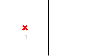
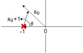
Let H(s)=1s+1 \text{H}(s) = \frac{1}{s+1}

The pole-zero plot on ss-plane is

drawing

Evaluating H(s)\text{H}(s) at any point at s=s0s = s_0 in the ss-plane

H(s)∣s=s0=1s0+1\text{H}(s)|_{s=s_0} = \frac{1}{s_0 +1}

drawing

H(s)∣s=s0=∣H(s0)∣ej∠H(s0)\text{H}(s)|_{s=s_0} = |\text{H}(s_0)| e^{j\angle \text{H}(s_0)}

∣H(s0)∣=1∣s0+1∣|\text{H}(s_0)| = \frac{1}{|s_0 + 1|} and ∠H(s0)=θ\angle \text{H}(s_0) = \theta

Given a rational system function:

H(s)=∏∗i=1M(s−zi)∏∗i=1N(s−pi)and ROC N>M\text{H}(s) = \frac{\prod*{i=1}^{M} (s-z_i)}{\prod*{i=1}^{N } (s-p_i)} \quad \text{and ROC~} N>M

∣H(s)∣s=s0=∏i=1M(s−zi)∏i=1N∣s0−Pi∣|\text{H}(s)|_{s=s_0} = \frac{\prod_{i=1}^{M} (s-z_i)}{\prod_{i=1}^{N }|s_0 - P_i|}

∠H(s)∣s=s0=∑i=1M∠(s∗0–z_i)−∑∗i=1N∠(s0–Pi)\angle \text{H}(s)|_{s=s_0} = \sum_{i=1}^{M} \angle(s*0 – \text{z}\_i) - \sum*{i=1}^{N} \angle (s_0 – P_i)

For any LTI system cos⁡(ωo)→∣H(jωo)∣cos⁡(ωot−θ) \cos({\omega_o}) \rightarrow |\text{H}(j\omega_o)|\cos({\omega_ot-\theta})

and θ=∠ H(jω0)\theta = \angle ~\text{H}{(j\omega_0})

where ∣H(jωo)∣→magnitude response|\text{H}(j\omega_o)| \rightarrow \text{magnitude response} and ∠H(jωo)→phase response\angle \text{H}(j\omega_o) \rightarrow \text{phase response}

Example:

Consider the input x(t)=cos⁡(ω0t)\text{x}(t) = \cos(\omega_0 t) for a system with transfer function H(s)=1s+1\text{H}(s) = \frac{1}{s+1} and ROC Re{s}>−1Re\{s\} > -1

cos⁡(ω0t)→11+ω02cos⁡(ωot−θ)\cos(\omega_0 t) \rightarrow \frac{1}{\sqrt{1+\omega_0^2}} \cos({\omega_ot-\theta})

where θ=tan−1(ω0)\theta = tan^{-1}({\omega_0})

Output signal magnitude is ∣H(jωo)∣=11+ω02→|\text{H}(j\omega_o)| = \frac{1}{\sqrt{1+\omega_0^2}} \rightarrow Low pass filter